Holes
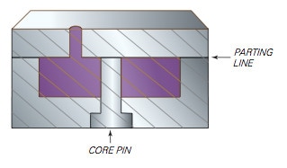
A hole or I.D. is created in a part by inserting a core pin in the cavity.
Holes at a right angle to the mold parting line are relatively easy to produce since the core pin is parallel to the injection path.
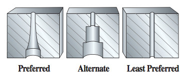
The normal shrinkage process, however, can cause the part to cling to the core as it cools in the mold. In order to facilitate ejection of the part from the mold, a draft should be incorporated along the length of the hole.
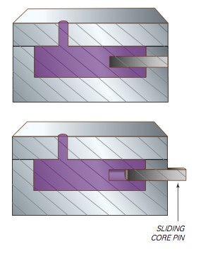
Holes that are parallel to the mold parting line call for the use of a sliding core that automatically retracts from the part as the mold opens. The use of sliding cores adds to the cost and complexity of tool design and construction.
If a hole does pass completely through a part, or if the part contains holes on more than one side, the mold must be designed to hold the part on a specific side of the open mold to facilitate automatic parts unloading.
Long, fragile cores tend to warp or break under continuous use due to the heat and pressure of their operating environment. The size of the core pin, and thus the diameter of the hole, should therefore be maximized whenever possible, particularly at the base, to ensure the stability of the pin. A useful rule of thumb to remember when designing part holes is the “2.1 rule”: The height of the hole should not be more than twice its diameter.